When you design a motorcycle frame, one of the most important aspects to consider is the frame stiffness (torsional, lateral, and braking). During the design stage, it is possible to calculate the stiffness with FEA (Finite Analysis Method).
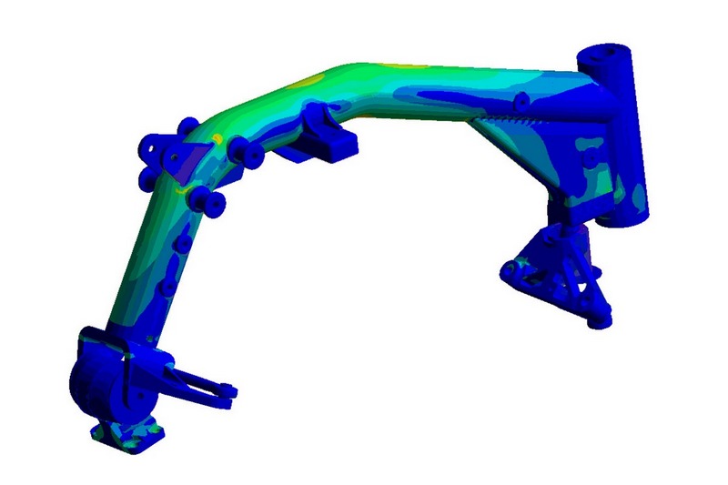
But theory is one thing and practice another, even more with a frame as the Buell XB one (this applies also for the BOTT XR1 frame) which is clamped to the engine using the Uniplanar system patented by Erik Buell. This system allows isolating the frame from the engine vibrations. To do it the frame is clamped to the engine through 2 big rubber blocks which allow the engine to move freely in a vertical and longitudinal way with respect to the frame. There are several “tie rods” that avoid that the frame can move in a lateral way with respect to the engine. These tie rods provide a large extent both the torsional and lateral stiffness.
All those elements (rubber blocks and tie rods) add extra complexity to the theoretical calculation of the frame stiffness, for this reason, it is very interesting to measure the stiffness.
Back in 2008 I designed and built a tool to measure motorbike frames stiffness. It is a simple and practical tool, which allows us to measure both lateral and torsional stiffness of frames and swingarms. This tool is not valid to obtain absolute stiffness values, but it is very useful to compare frames, and even more to compare design modifications of a frame.
The operation is very simple, we apply a load and at the same time, we measure the deformation using a dial gauge. We increase the load little by little and we take measurements. With this information, we can draw a graphic that gives us stiffness.
We use this tool to develop our own frames, and we also give this service to other frame builders.
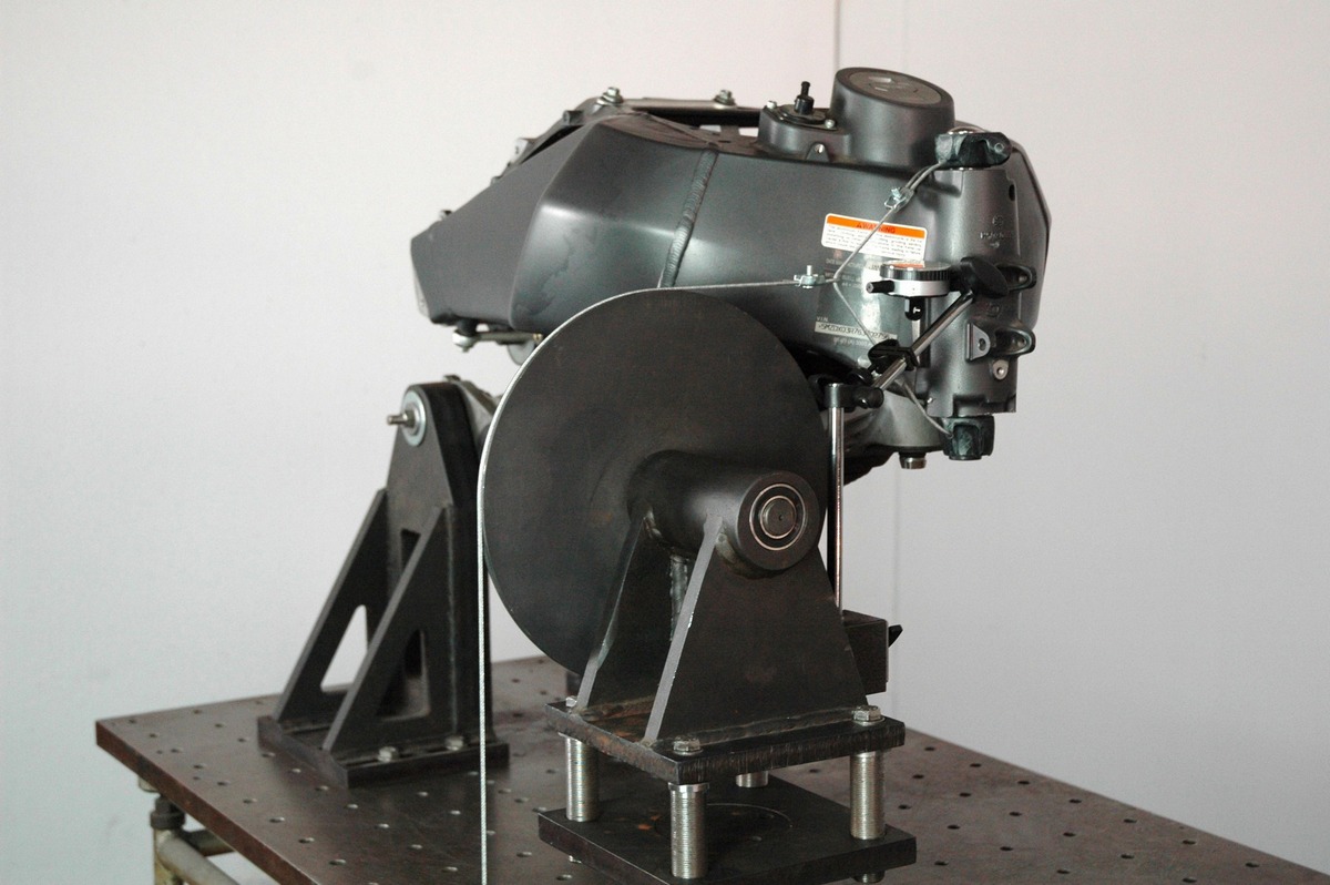
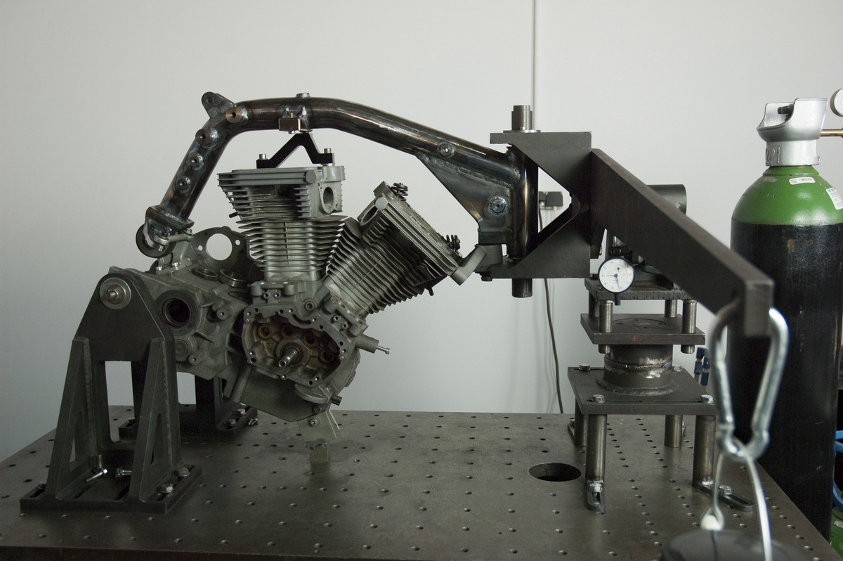
The next photo shows the measuring of the lateral stiffness of a Buell XB frame.
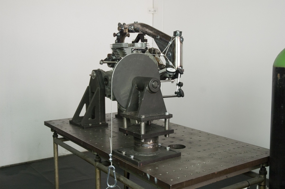
Here we are doing the same with a BOTT XR1 frame.
The next photo shows the measuring of torsional stiffness of a Buell XB frame.
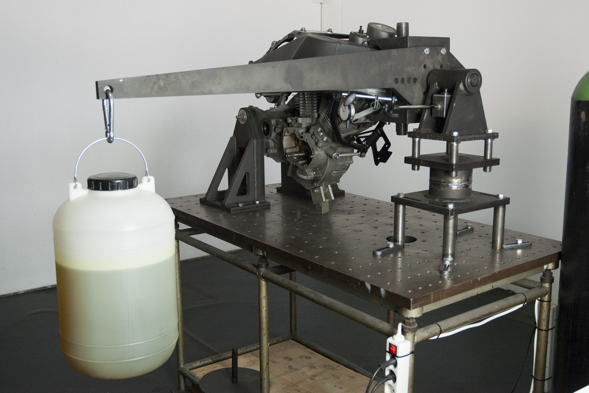
And here we do the same with our BOTT XR1 frame.
As I mentioned previously, these measures are not valid to get absolute values, but they are very useful to understand the behavior of our frames. In this way, we have data to work with, which allows us to compare modifications and new designs.
In any case, the target is to apply loads similar to what the bike will experiment in real life. We do not pretend to see how much load the frame can handle. The loads we apply are always small. The target is to measure the frame stiffness. It is the same case as a machine used to measure spring stiffness.
Every year we give the opportunity to one or two engineering or industrial design students, that do an internship or their final degree project with us. This year Ferrán Gallego, an engineering student from the Valencia Polytechnic University, made his project measuring frame stiffness with our tool.
The BOTT XR1R that raced in Pikes Peak had the last evolution of our frame (steel, because the Pikes Peak rules don’t allow to use titanium frames) designed to be stiffer because the XBRR engine has 50% more power than the standard XB engine that we use in our street bikes. Now we will include some of these modifications to our standard frames.
Next year we will come back to Pikes Peak and we are already working on the evolution of the BOTT XR1R.
Regarding the frame, next step will be to add strain gauges that will allow us to measure load values in specific points. We will measure these loads both in our laboratory (using the same tool of the photos above) and also with the bike on the track. The XR1R has already a data acquisition system that we will use to log this information.
A very interesting part to mount strain gauges on are the tie rods of the Uniplanar system, because all the side loads generated in the corners are going through them. Using strain gauges we can convert the tie rods into load cells that will measure in a continuous way all the loads going through them.
We will show it in another post.
this shows how pro you are!!!
very well done David
Thank you Sami! 🙂