In the design phase of the Morlaco 2 chassis, one of the key aspects to consider is its stiffness. Since this motorcycle features an alternative front end, the steering head is “floating” at the end of the suspension’s A-arms. Therefore, when measuring stiffness, we must also consider the rigidity of these A-arms.
What is chassis stiffness and why is it important?
The chassis is one of the most crucial components in motorcycle design, as it largely determines how the bike behaves in various situations. When we talk about chassis stiffness, we are referring to its ability to resist deformation when forces are applied.
Essentially, when we measure the stiffness of a chassis, we do it the same way as measuring the stiffness of a spring to obtain its “K” stiffness constant: we apply a force and observe how much it deforms. By dividing the force by the amount of deformation, we obtain the stiffness value.
To measure chassis stiffness, we do not need to calculate the maximum loads it will be subjected to. We simply need to apply a load that makes the chassis operate within its elastic zone.
We primarily measure three types of stiffness in a chassis:
Lateral stiffness: This measures the flexing of the chassis when forces are applied from the sides. In practice, this is measured either by anchoring the chassis at the swingarm pivot and applying a lateral force at the steering head, or by anchoring the steering head and applying a lateral force at the swingarm pivot.
Torsional stiffness: This refers to the chassis’s ability to resist twisting. It is measured by anchoring the chassis at the swingarm pivot and applying a torque at the steering head (this can also be done in reverse).
Longitudinal stiffness: In this case, we simulate the deformation that occurs during braking. We anchor the chassis at the swingarm pivot and apply torque as if trying to push the front wheel backward.
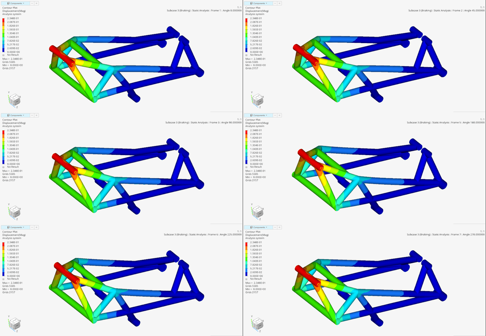
The following image shows (exaggeratedly) how the chassis deforms during braking. The red areas indicate where the greatest displacement occurs, while the dark blue areas show the least movement.

How we measure stiffness at Bottpower
In the design phase, we calculate the chassis stiffness using Altair HyperWorks, a set of advanced tools that allow us to measure and analyze various aspects of stiffness through finite element analysis (FEA).
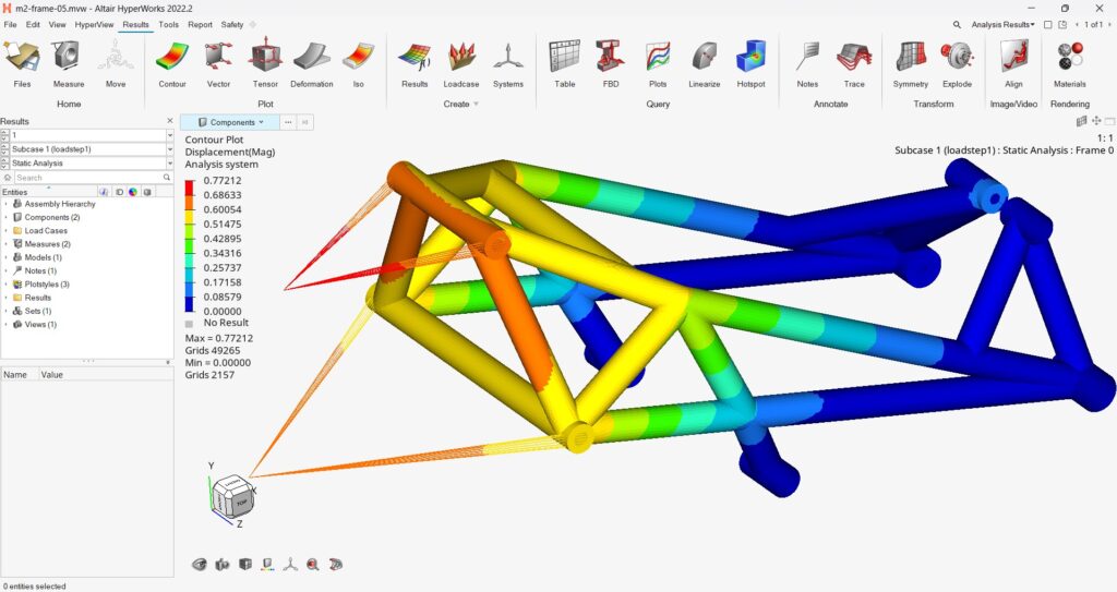
In the next image (a screenshot from HyperView), you can see a simulation showing the study of lateral stiffness. The colors in the image represent the magnitude of displacement, with red indicating areas of greater deformation and blue representing those that have moved the least. To perform these calculations, we establish our own hypotheses for the analysis. This includes how we account for the stiffness of the engine and other components, such as the front suspension’s A-arms.

The relationship between different types of stiffness
An interesting aspect is that we do not aim to maximize stiffness in all directions but rather to find a balance. A chassis that is too stiff in every direction can be less comfortable and more demanding for the rider. On the other hand, well-adjusted stiffness in each axis can result in a smoother and more controlled ride. Our goal is to find the ideal balance between lateral, torsional, and longitudinal stiffness, providing agility without compromising stability.
In general, we aim for moderate lateral stiffness and higher torsional and longitudinal stiffness.
Controlled flexibility in the lateral direction allows for greater tire slip, which helps to dampen oscillations and enhances both stability and traction.
By the way, it’s interesting that all the motorcycles we’ve built at Bottpower have some particularities when it comes to stiffness. The BOTT M210 (the Moto2 bike we built in 2010) featured a ‘stemless’ steering head, which significantly increased the damping of lateral movements in the front end. At that time, Moto2 bikes were using Dunlop tires, which caused many problems with front-end chattering. Our bike never experienced those issues.
The XR1 also has very unique stiffness characteristics, with the main chassis mounting points to the engine using silent blocks, and ‘tie-rods’ that provide both lateral and torsional stiffness to the bike.
Another key aspect in the design of the Morlaco 2 is the stiffness of the front fork, but that will be the topic for another post.
Physical validation: the next step
Once we have built the first physical prototype of the chassis, our plan is to validate the simulation results with real-world measurements. We will use our chassis stiffness measurement rig to obtain real data and compare those results with our FEA predictions. This will not only allow us to refine the design if needed, but also give us extra confidence that the Morlaco 2 chassis meets our performance expectations.
We hope you’ve found this glimpse into our workflow interesting. At Bottpower, we believe that every small adjustment and improvement we make in design brings us closer to the perfect motorcycle. If you enjoy this type of technical content and want to learn more about the development of the Morlaco 2, stay tuned to our blog and social media channels!